I want to simulate an existing network
Tested for version CF build number 109802
This tutorial focuses on the simulation of an existing network in the computational framework (CF) as well as the possibilities to alter (sub-) scenario’s and to change the imported heat demand.
This tutorial shows the steps to find the answer to the following questions:
This tutorial uses the ESDL created in the tutorial: I want to create a network
To achieve these results the following workflows and packages are used:
|
The network is loaded into the Computational Framework (CF), which allows to alter heat demand, simulate and optimize heat networks, define (sub) scenario’s and related modifiers. |
|
In the CF environment, CHESS is used to simulate the network. |

If these packages haven’t been installed yet, please follow the tutorial: I want to install the toolkit
1 |
How to import an existing network in the computational framework (CF) |
1.1 |
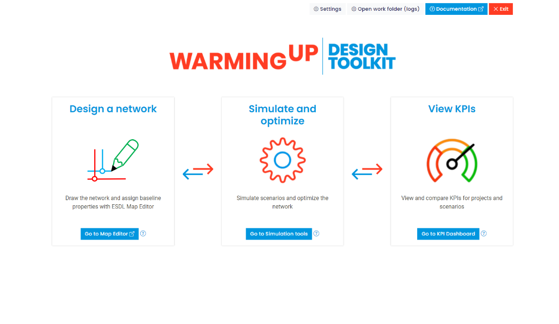
Start the WarmingUP Design Toolkit by clicking WiseDesignToolkit.cmd in the installation folder. Your start screen looks like this:
|
1.2 |
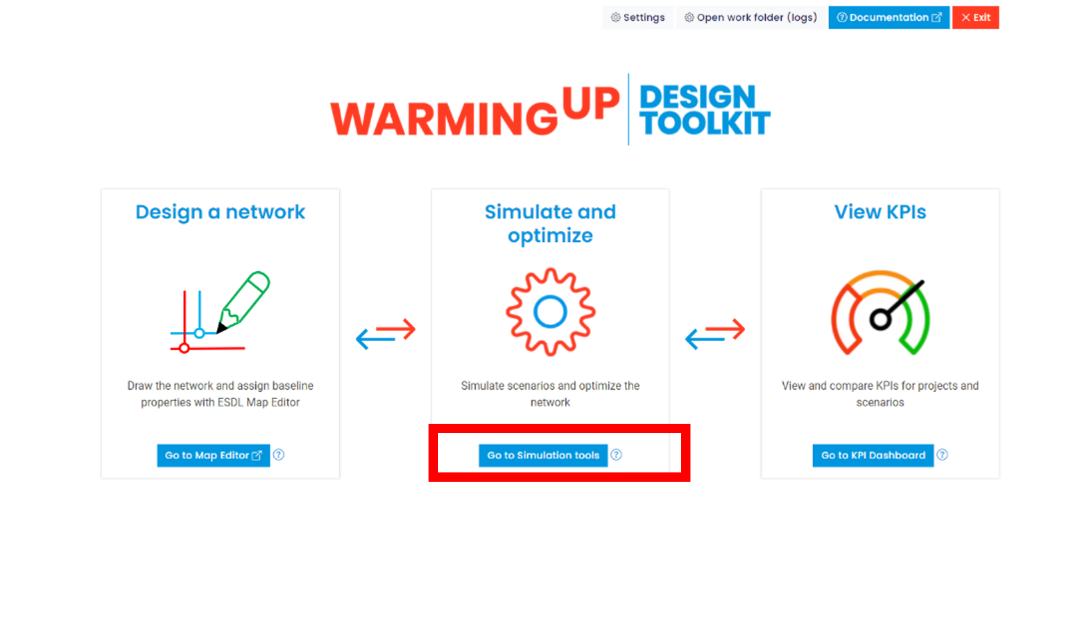
Click the button “Go to Simulation tools”.
|
1.3 |
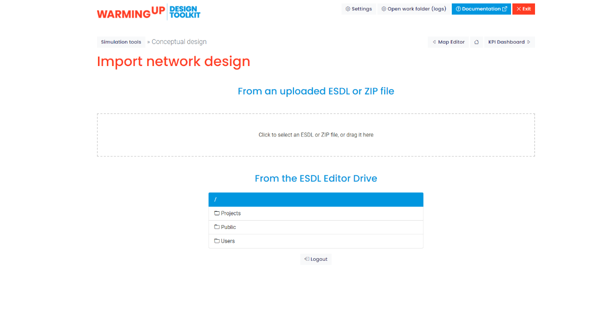
Under the tab “Conceptual Design”, click the button “Import Network Design”.
Note: This tutorial will focus on an existing project on the ESDL Editor Drive |
1.4 |
Navigate to your saved ESDL file and open it. |
1.5 |
Select the desired location of the folder to store the project |
1.6 |
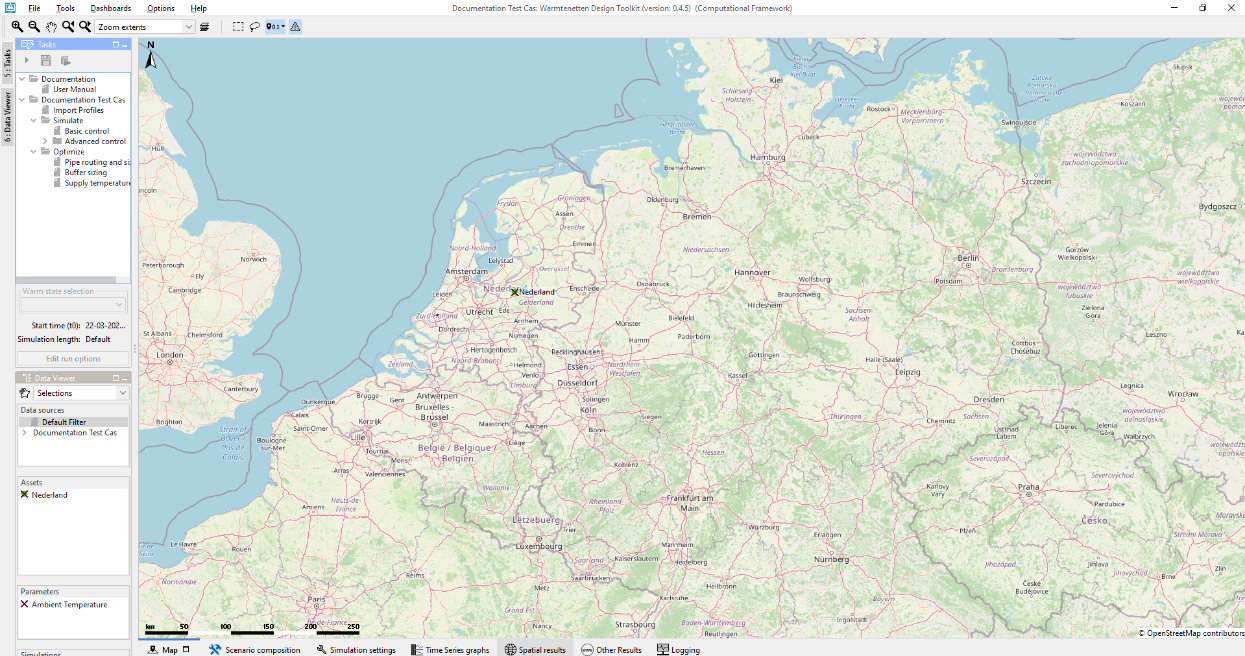
Specify the project name and click OK. The Computational Framework starts up, and should look this (have a bit of patience the first time you start it)
|
2 |
How to simulate your existing network |
2.1 |
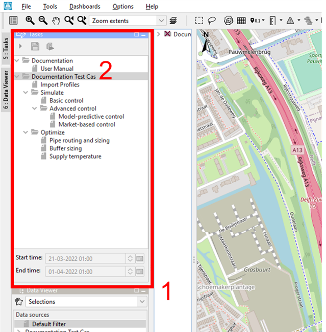
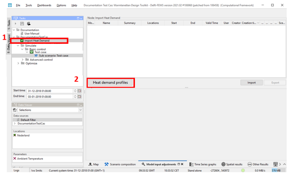
Navigate to the Tasks panel (1) (upper left) and expand the project (2). The tasks panel gives an overview of the possible tasks/models within CF. In this tutorial we will apply the tasks of importin heat demand profiles and running a simulation with basic control.
|
2.2 |
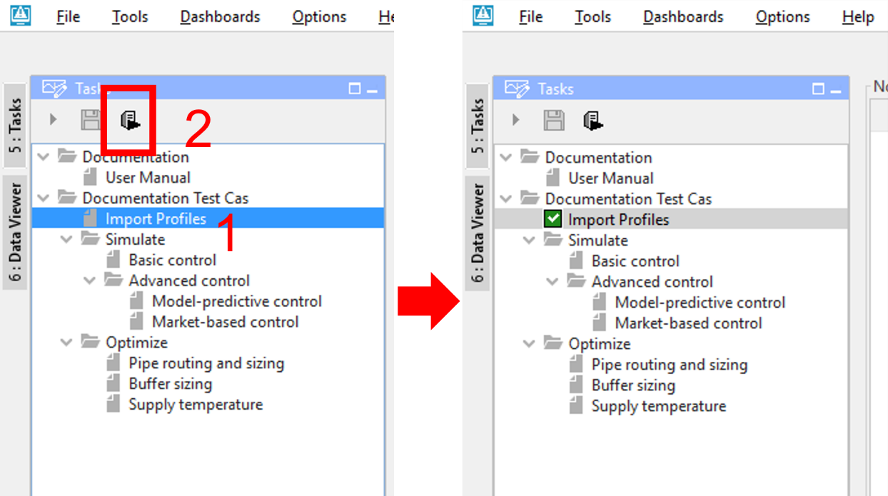
Select ‘Import Profiles’ (1) and click on the Run button (2). This step imports the heat demand profiles as defined in the heat network design in the ESDL MapEditor .
|
2.3 |
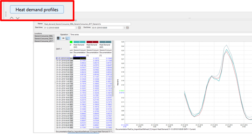
Informative: If you want to check or alter the imported heat demand, click the “Heat demand profiles” button.
Note: the topic 6: How to change the imported heat demand? is described further in this tutorial. |
2.4 |
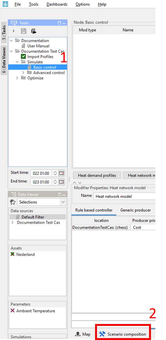
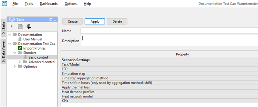
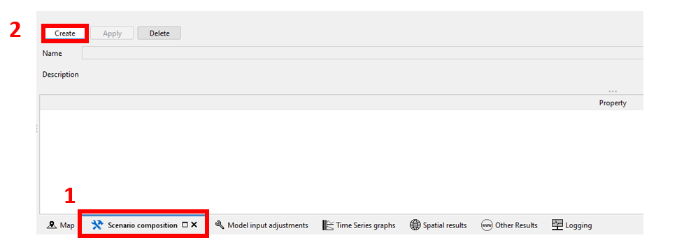
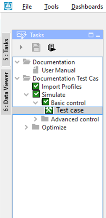
In order to correctly simulate your network, it is needed to compose a scenario. In a scenario a selection of logical attributes is bundled. The abilities to alter scenarios are described in 4: How to alter scenarios, in this tutorial. Click on Simulate-> Basic Control in the Tasks panel (1) then click Scenario composition (2).
|
2.5 |
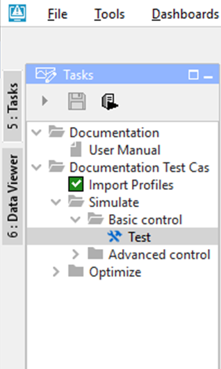
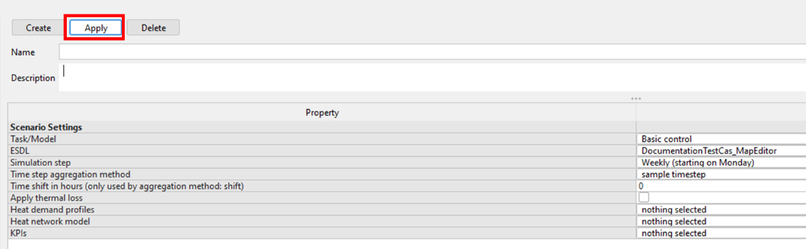
Click create, specify a desired name and click apply
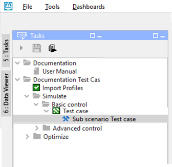
The scenario is now created and it should look like this in the Tasks panel
|
2.6 |
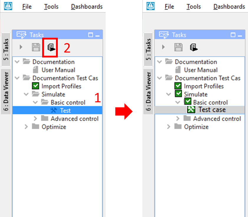
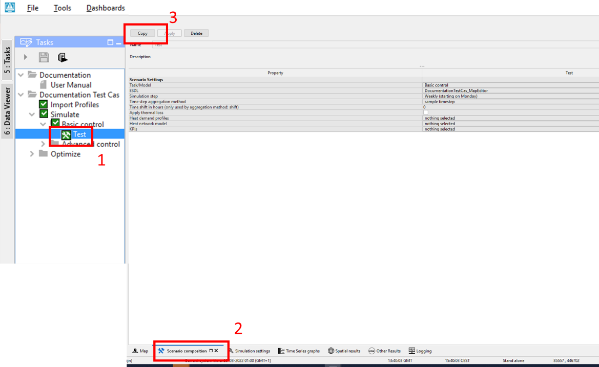
Select (1) the case (here called “Test”) in the Tasks panel and click the Run (2) button
|
3 |
How to view results after simulating your network |
3.1 |
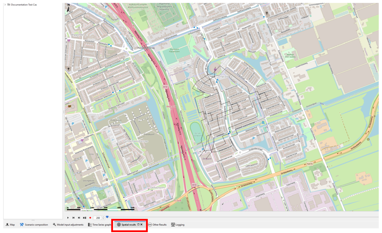
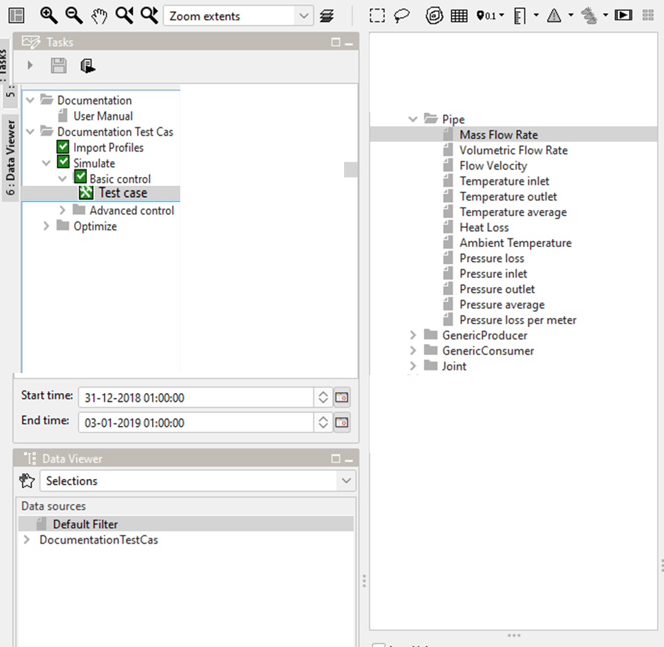
Within CF there are multiple ways to view the results of a simulation. The following steps describe the actions needed to be able to view these results. To view spatial results Select the tab ‘spatial results’ and zoom to the existing network
To view the spatial results, select any type of asset and result you like in the results panel top left next to the tasks panel |
3.2 |
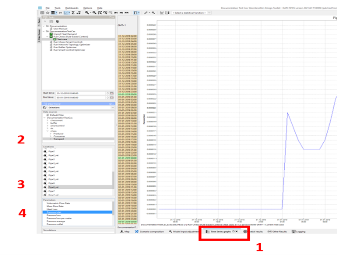
To view the results in the time series tab
|
4 |
How to alter scenario’s |
4.1 |
In order to compare different scenarios, it is possible to alter and add scenarios within CF. The following steps describe the abilities to alter the scenarios. To start a scenario composition
|
4.2 |
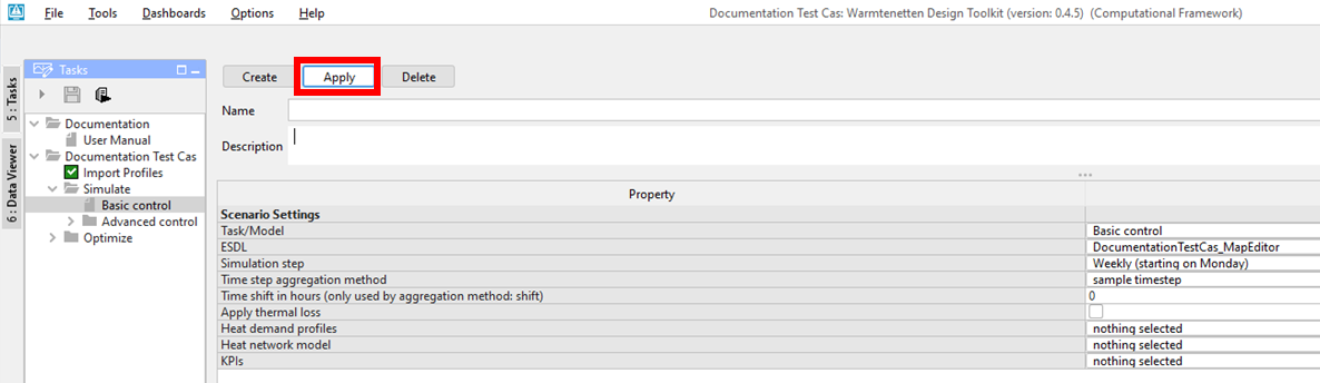
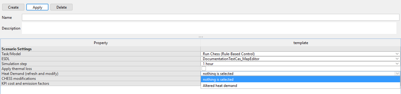
Within the scenario composition manager, you can specify a scenario by its settings:
|
4.3 |
To save the composed scenario select ‘Apply’ (3)
|
4.4 |
Eventually the result should look like this
|
5 |
How to create a-sub scenario |
5.1 |
To create a sub-scenario on an existing scenario
|
5.2 |
Within the scenario composition manager, you can specify the sub-scenario by changing any setting you would like:
|
5.3 |
To save the composed scenario select ‘Apply’ (3)
|
5.4 |
Eventually the result should look like
|
6 |
How to change the imported Heat Demand |
6.1 |
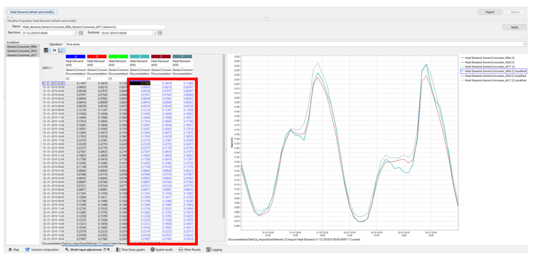
*Within the simulation of the ESDL model it can be useful to alter the heat demand. This altered heat demand is saved with a unique name and can be chosen within a scenario. This enables the possibility to compare simulation results based on different heat demands. * To change the imported heat demand
|
6.2 |
It’s possible to alter the heat demand manually or automatically Manually: Alter the values one by one or by copy paste form a spreadsheet program in the table itself (blue numbers can be altered)
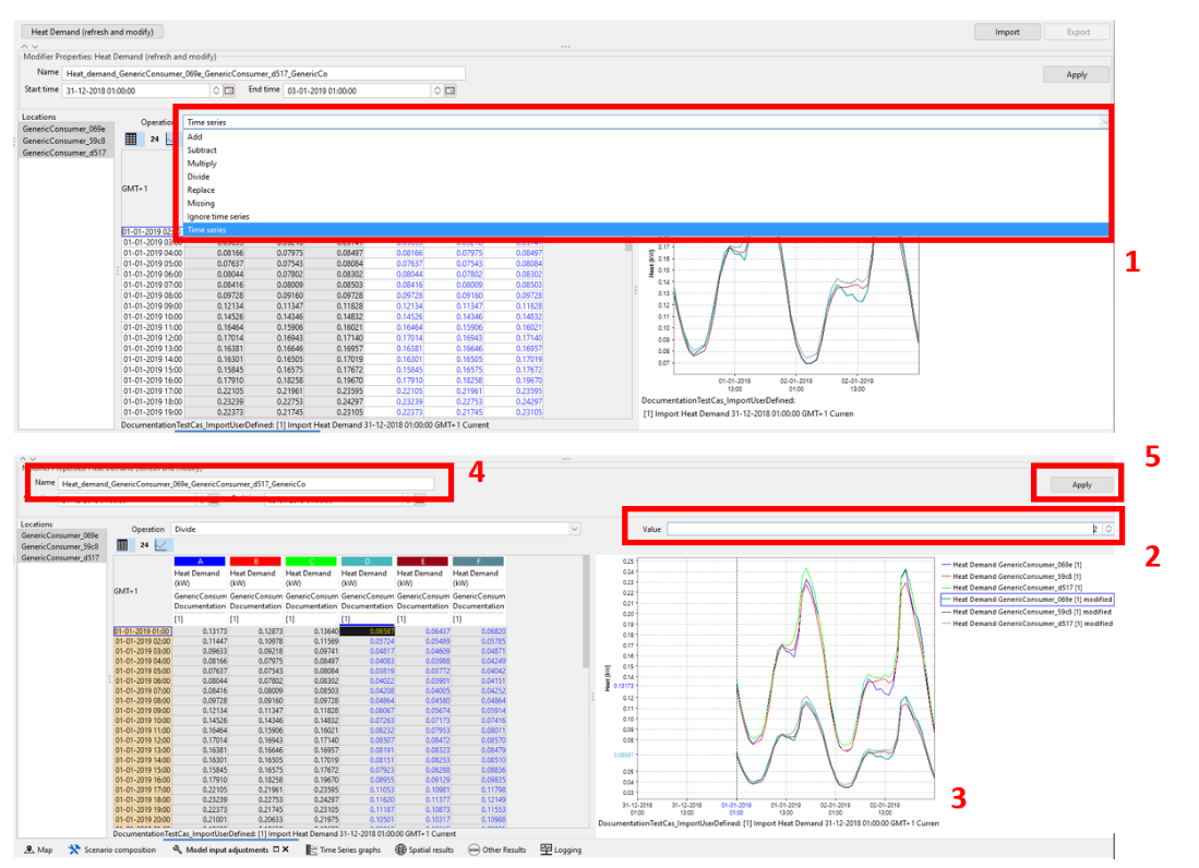
Automatically:
|
6.3 |
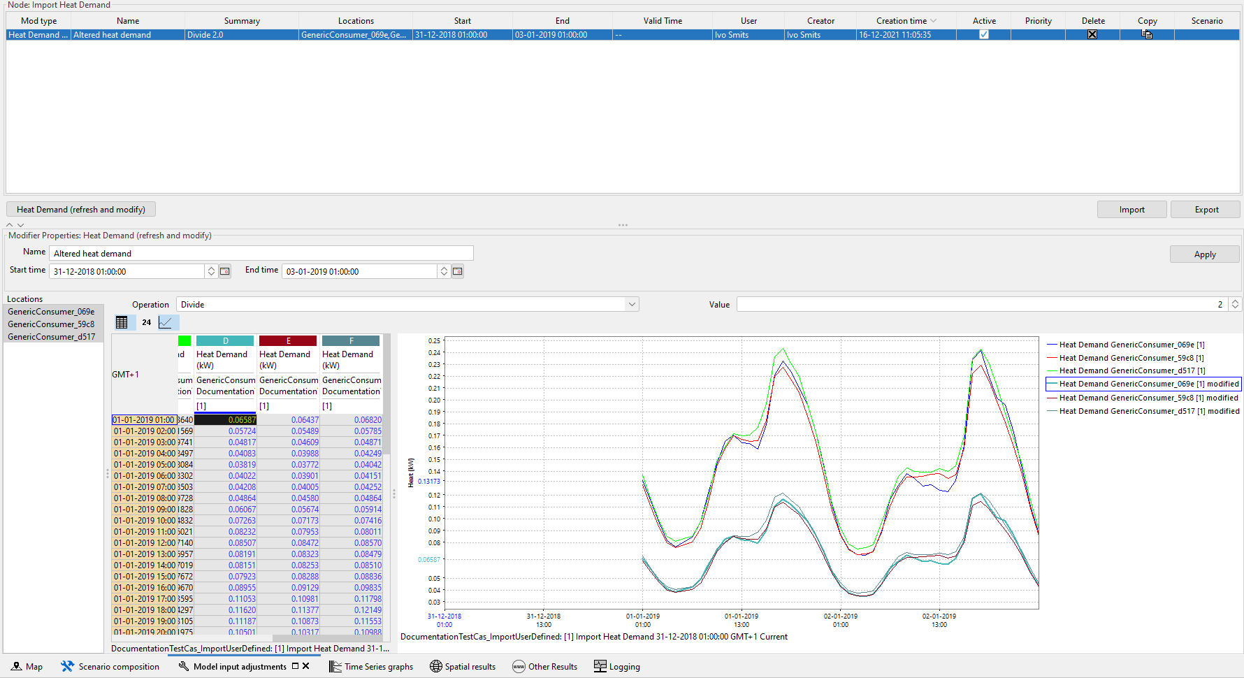
The altered heat demand is saved and can be selected in any (sub) scenario *Note: following pictures 1 and 2 are informative *
|