I want to optimize the pipe sizing
Tested for version beta 0.4.2 of the WarmingUp Design Toolkit.
The tutorial deals with optimizing the topology of a heat network. This tutorial shows the steps to find the answer to the following questions:
How to minimize pipe sizing in the network?
This tutorial builds upon the preceding tutorial topic ‘I want to simulate an existing network’, see I want to simulate an existing network — Warming Up Design toolkit 0.3 documentation (readthedocs-hosted.com)
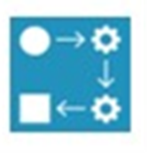
To achieve these results the following packages are used:
|
The Computational Framework is used to run the workflows and create scenarios |
|
Within the Computational Framework CHESS is used to simulate the network. |
|
Within the Computational Framework the Energy Network Topology Optimizer is used. |

1 |
How to minimize pipe sizing in the network? |
|---|---|
1.1 |
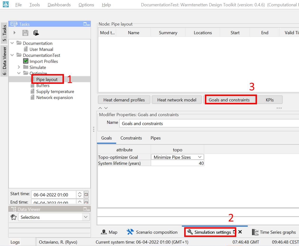
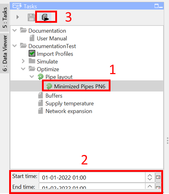
1) Go to Optimize-> Pipe layout in the Tasks panel.
2) Click on the ‘Simulation settings’ tab
|
1.2 |
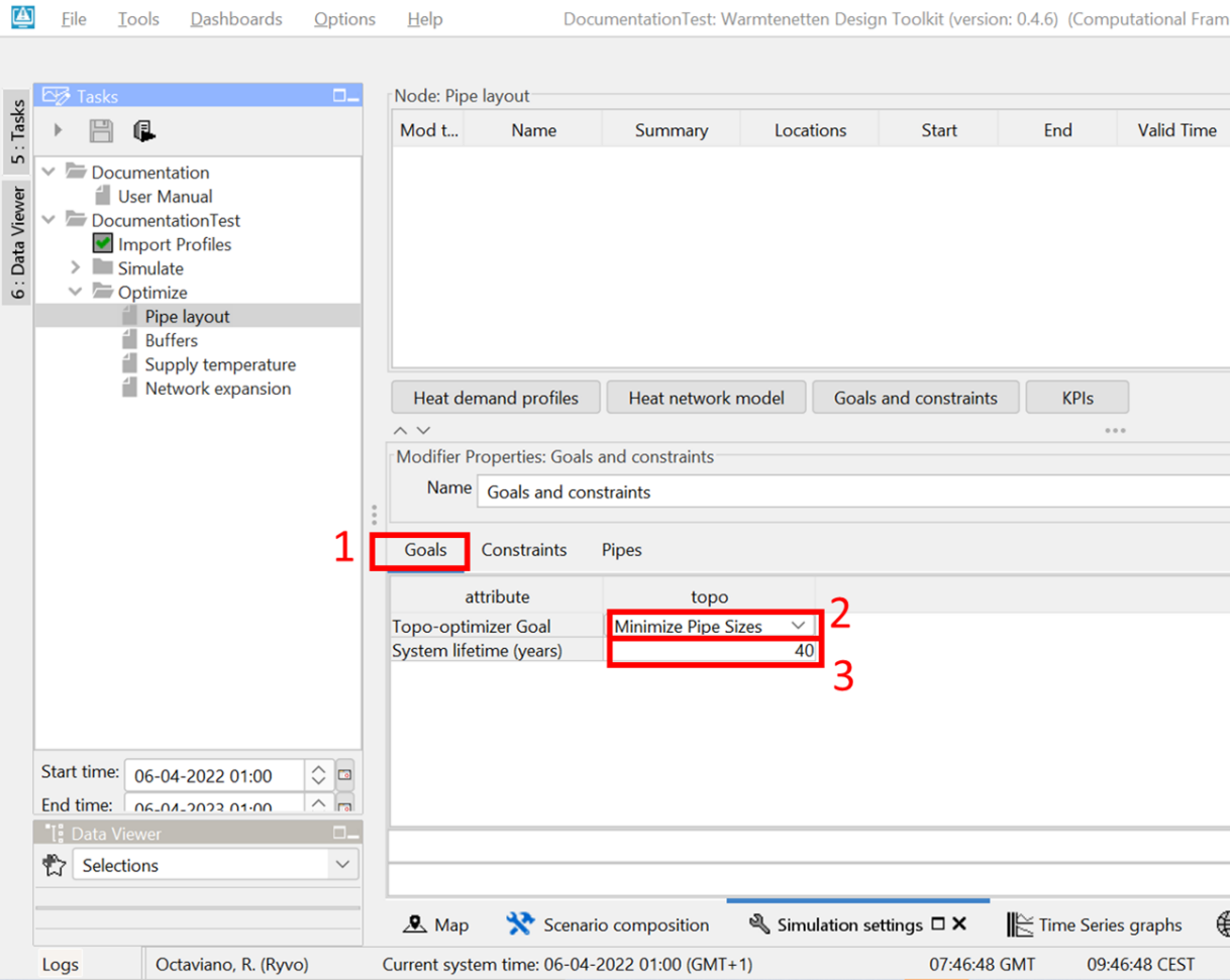
Defining the goals:
|
1.3 |
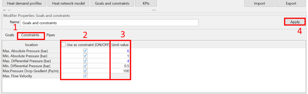
Defining the constraints:
|
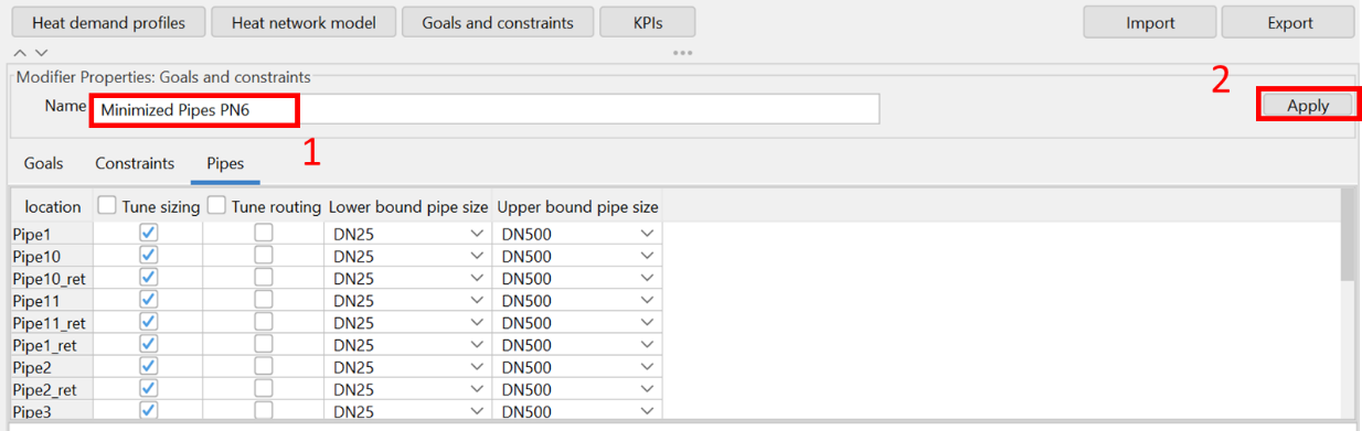
1.4 |
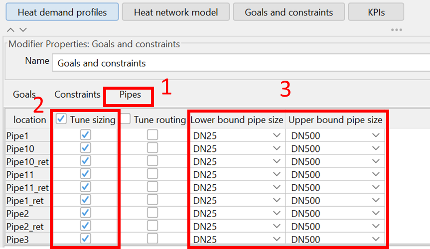
Defining bounds on pipe sizes and selecting the pipe characteristics to be optimized/tuned:
|
1.5 |
Creating the scenario modifiers
|
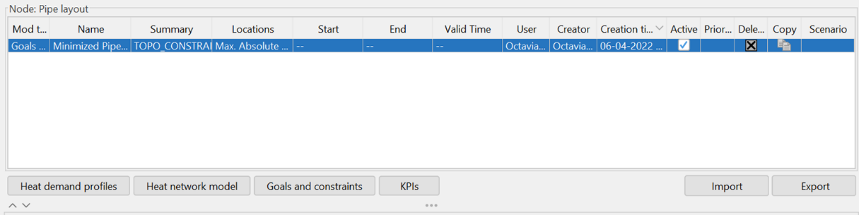
1.6 |
The desired scenario modifier is now created and can be used in a scenario.
|
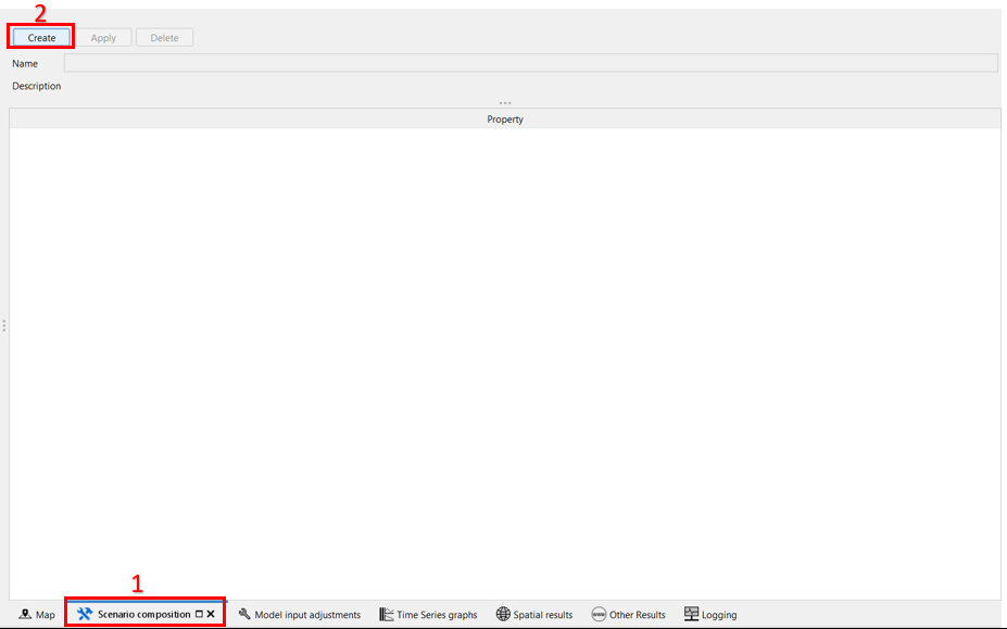
1.7 |
Creating a scenario with the topo-optimizer modifier
|
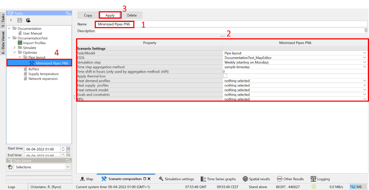
1.8 |
Creating a scenario with the topo-optimizer modifier
|
1.9 |
Running the scenario
|
1.10 |
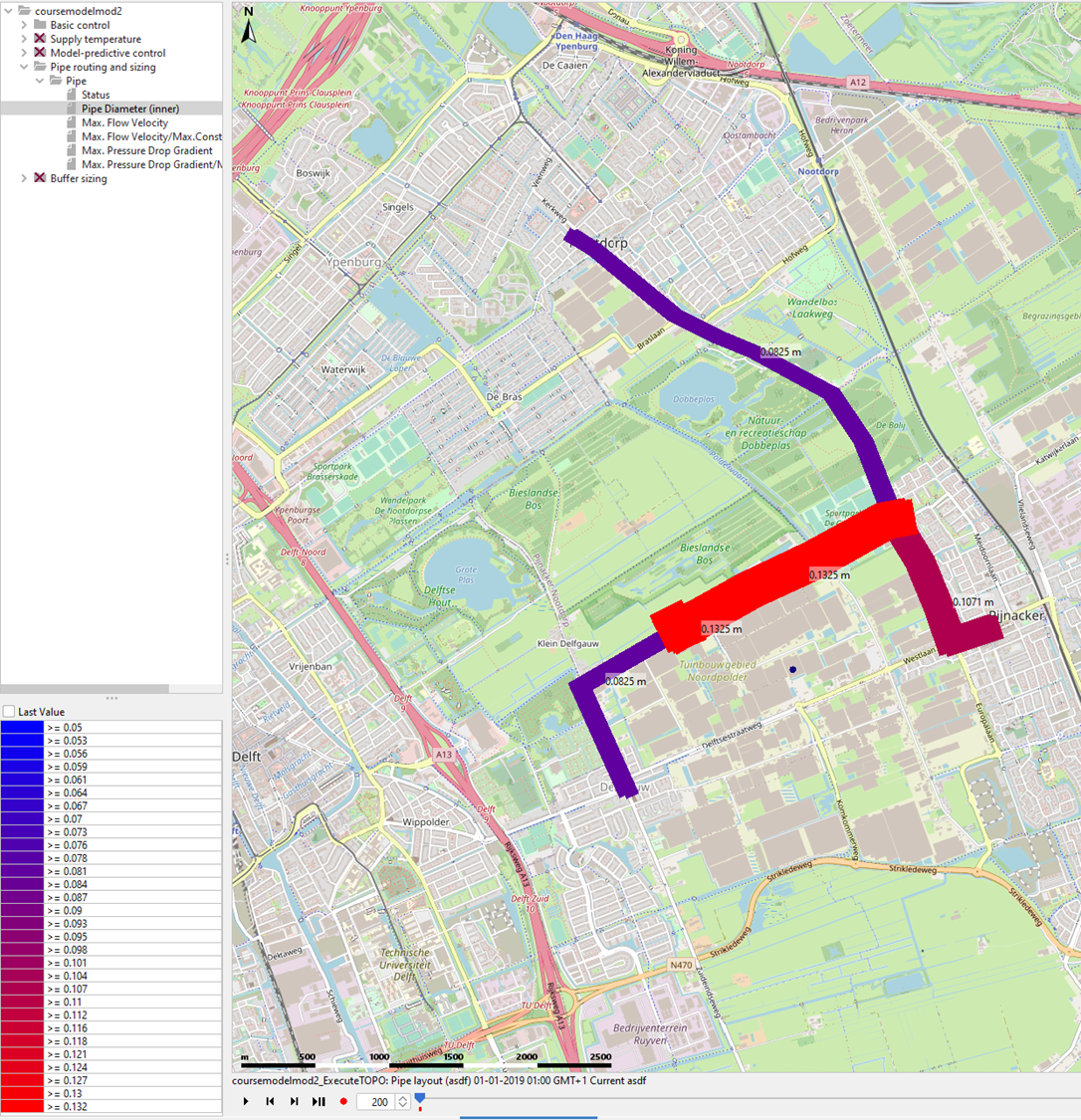
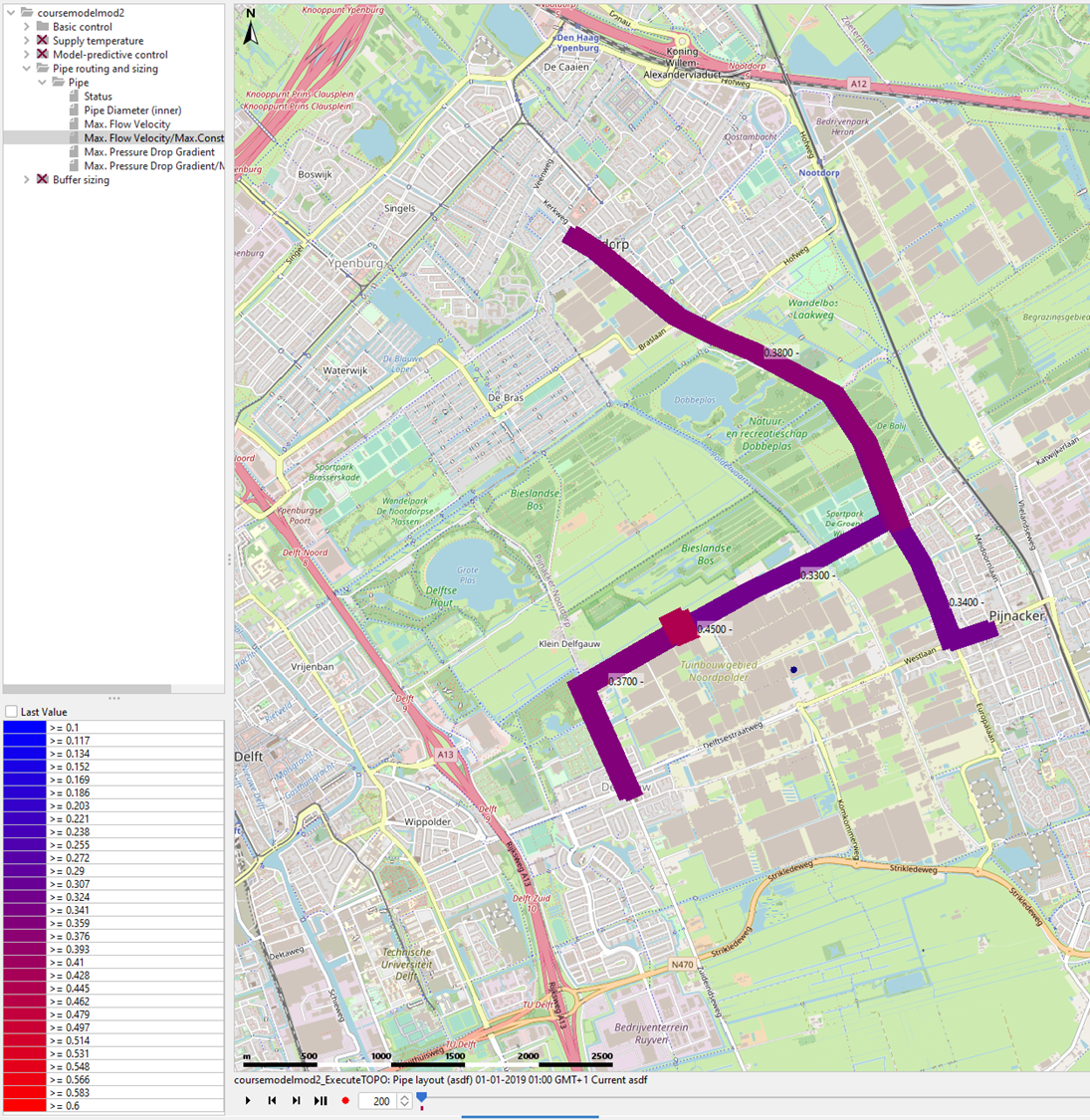
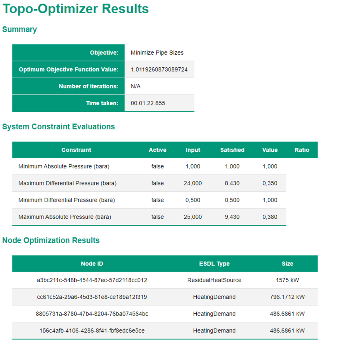
Viewing the results There are different ways to inspect the results after optimizing the pipe layout:
|